This tip complies with ASME Y14.5-2009 and ISO1101:2012
A drawing is a binding contractual document that has financial implications, therefore it has to be clear and unambiguous!
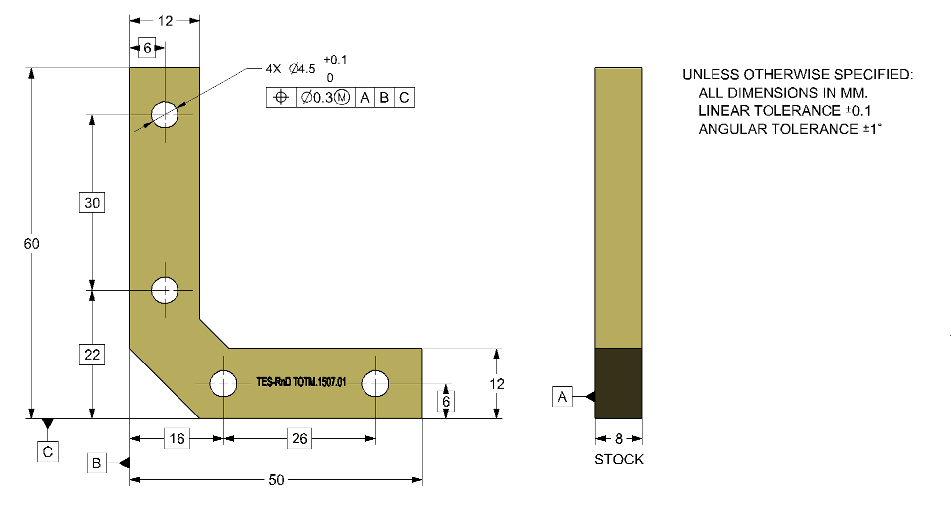
A General Tolerance definition that was commonly used in industry in the past:
UNLESS OTHERWISE SPECIFIED:
DIMENSIONS ARE IN MILIMETERS
LINEAR TOLERANCE: ±0.1
ANGULAR TOLERANCE: ±1°
allows deviations that may be “slightly” beyond expectation!
For illustration purposes, Figure 1 shows a drawing of a *** try-square (זוויתן) ***
The following figure shows a part before the reaming of the holes.
Does the part meet the drawing requirements?
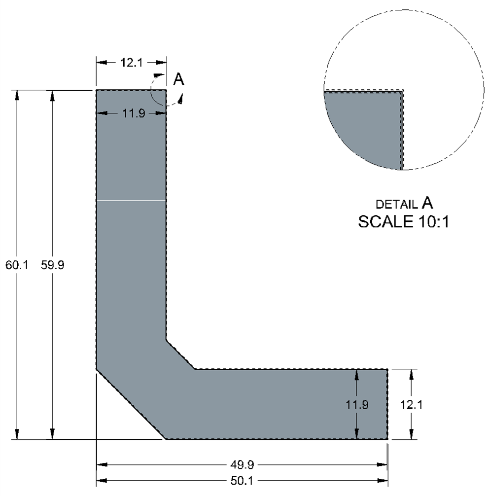
The part was measured and the results are graphically illustrated in the following figure:
• On the right side, the vertical facet was selected as a measurement base;
• On the left side, the bottom facet was selected as a measurement base.
Even though the part looks warped
- the distance between all opposing points measured is exactly the nominal value;
- The angle does not deviate from the angular tolerance limit (91°).
Which is the correct angular measurement (right or left)?
- They are both correct; an angle with an angular tolerance is not linked to or affected by datums!!!
Does the item meet the drawing requirements?
- Depends who you ask!!!
- No specific standard is indicated, so the valid standard is “Standard Whatever – Local Edition”.
Is the item usable?
- It is not possible to tell based on the drawing alone.
So, what can be done?
If the intention was that the deviation limits would be bound between parallel planes that maintain the angles and sizes as in the following figure:
then the part received is not functional
and a general tolerance for the profile is the right choice.
Do not forget to note a standard and an edition according to which the drawing should be interpreted;
If it’s not written down – it doesn’t exist
In summary:
A drawing is a binding contractual document.
Reality is not perfect, so you need to define deviations within limits that would not affect the functionality of the item. Lacking definitions or having partial ones, the drawing would be open to interpretation.
In the example shown, the general tolerance limits did not correspond with the actual need, and obtaining a usable item is at the mercy of the supplier. Although in most cases there will not be a problem, it is important to remember that defining a level of accuracy beyond what is needed has a price
- the item will be more expensive
- it will take more time to produce
It is the responsibility of the designer to specify the functional boundaries! Even if they are broader than the technological boundaries, in order not to rule out new technologies that may be faster and / or cheaper…
For this reason, in today’s competitive outsourcing world, it is important to define a specification of geometric requirements which is clear and unambiguous.
Questions? Ideas? Suggestions?
Write to us –info@TES-tec.net


