(This tip is compliant with ASME; for ISO it is necessary to add E to the dimensions of the wave diameter in Figure 1, a perfect envelope at MMC.)
A drawing is a contractual document, it has financial implications. If we want to avoid surprises, we must ensure a full definition of geometric deviation limits.
The following plot is imaginary but based on real events.
Wall Thickness Calculation
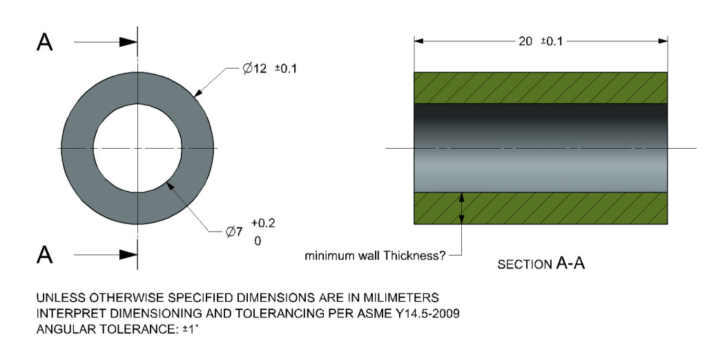
Figure 1 shows a spacer for an M6 threaded rod
Figure 1
Calculation of wall thickness in order to ensure that the extreme state is reasonable:
- Maximum diameter of the hole: 7.2
- Minimum diameter of the shaft: 11.9
Minimum wall thickness: (11.9-7.2) / 2 = 4.7 / 2 = 2.35
Surprising Result
Figure 2 shows the measurement of a produced part:
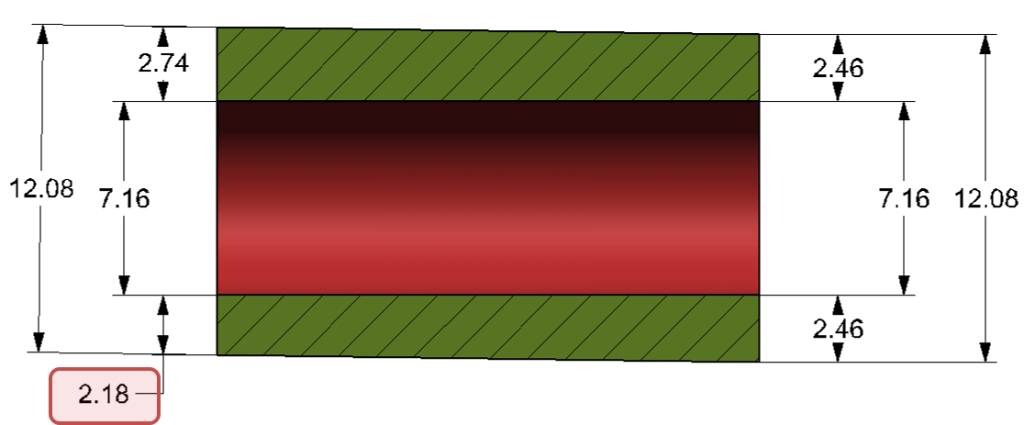
Wall thickness of 2.18 was received, smaller than the calculated minimum 2.35
For this part, the minimum wall thickness expected is:
(12.08-7.16) / 2 = 2.46
So, how did that happen?
The mystery explained
The real world is not perfect; each surface could have a deviation in size, form, angle or location.
It turns out that the produced part also has an angular deviation. The angular deviation between the wave and the hole in the part is shown in Figure 3
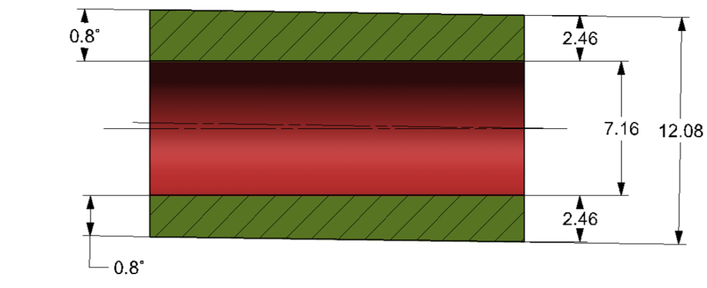
The general tolerance in the drawing determines angular deviation limits of ±1º.
The measured value – 0.8º, meets the drawing requirements, and explains the difference between the calculation and the measurement
20 x tan(0.8°) = 0.28
The conclusion is that in order to calculate the extreme states of wall thickness, the permissible deviation of the position and the angle must also be taken into account!
Calculation of the minimum wall thickness including an angular deviation:
- The hole at the upper deviation limit – a diameter of 7.4 (at LMC)
- The shaft at the lower dimension limit – a diameter of 11.9 (at LMC)
- A permissible angle deviation of ±1º allows a position deviation of 0.35 (for a longitude degree of 20 units)
(11.9 – 7.2 – 0.35) / 2 = 2.175
This calculation is still incomplete.
In Figure 3 on the right side of the part, the wave is concentric to the hole, but it is unrealistic to expect that there will be only an angular deviation;
it is also necessary to define the permissible deviation limits for the position of the wave in relation to the hole.
If we add to the drawing in Figure 1 a position deviation of ±0.1
then the minimum wall thickness is reduced to 2.075
And what about straightness deviation of the hole?
Full Definition
Any real surface is expected to have a deviation in size, shape, angle and position; geometric tolerances allow us to write clear, unambiguous geometric requirements specification.
In addition, geometric tolerances can consolidate a number of requirements into a single boundary, for example the position tolerance of the axis of the wave controls the deviation in position, angle, and form of the wave. In practice, the position tolerance sets the boundaries of the combined deviation of the three characteristics.
Figure 4 Part drawing with geometric tolerances
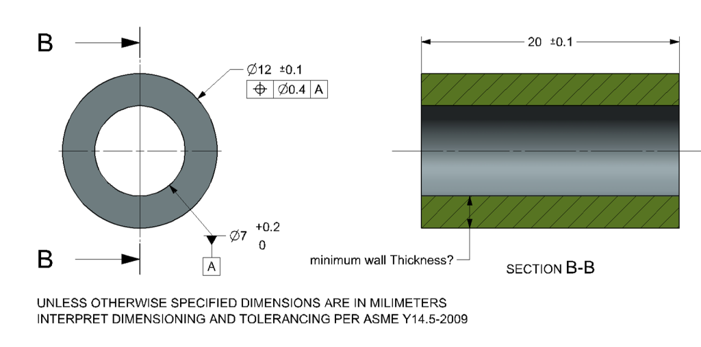
This time the limits of the permissible deviation between the wave and the hole are defined in full.
- The axis of the largest bounded cylinder is the measurement base (Datum A);
- The axis of the Shaft may have a deviation in position, angle and straightness up to the limit of the position tolerance zone – a theoretical cylinder with a diameter of 0.4 which is located on datum A.
We will get the extreme state of wall thickness when:
all deviations are taken into account (size, form, position, and location).
- For the hole:
- Size deviation – the hole at the upper dimension limit – a diameter of 7.2 (at LMC);
- Position and location deviation – there is no deviation because the hole is the only datum feature (it cannot deviate from itself).
- For the Shaft:
- Size deviation – the wave at the lower dimension limit – a diameter of 11.9 (at LMC);
- Maximum form deviation at LMC – a diameter of 0.2 (a diameter of 11.9 tangential to perfect form at MMC);
- Position and location deviation – the position tolerance, a theoretical cylinder with a diameter of 0.4, coaxial to datum A.
[ (12.0-0.1) – 0.4)) – (7.0 + 0.2) ] / 2 = 2.15
But this time it is guaranteed that this limit will be maintained for each part that meets the drawing requirements.
In summary
If it’s not written down, it doesn’t exist!!!
In order to avoid surprising results, every drawing should have full and unambiguous definitions.
Questions? Ideas? Suggestions?
Write to us –info@TES-RnD.com

