This tip complies with ASME Y14.5-2009, ISO 2692-2006
In many cases parts in an assembly are designed to mate simultaneously with more then one counterpart or feature, for example see Toy model truck below (figure 1). The Hood is designed to mate with both pins.
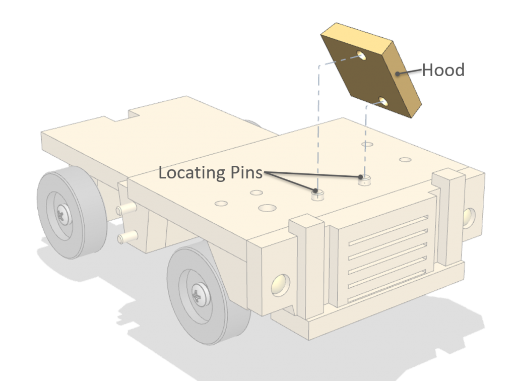
Figure 1
The drawing below (figure 2), depicts design intent. Both pin holes establish Datum B. In reality neither one has precedence over the other, location of the Hood will be determined by both pin holes simultaneously.

Figure 2
Common setup includes the following steps:
- Establish Datum A (figure 3)

Figure 3
2. Center on the Top holes (figure 4)
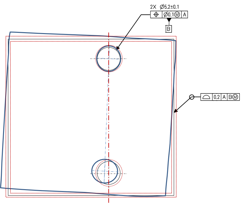
Figure 4
3. Align Second hole (figure 5)
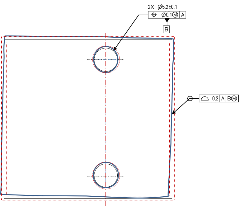
Figure 5
It looks like the Profile requirement is not met (figure 6)

Figure 6
Should the part be scraped?
The answer is: Not Yet!
The simulated Datum Frame (Plane – Orients, Top Hole – Locates, Bottom Hole – Orients) implies the Top Hole has priority over the bottom Hole. Top Hole and Bottom Hole Centers were established from the Unrelated Actual Material Envelope, Rather than the Related Maximum Material Boundary (ASME Y14.5-2009, Fig. 4-26, ISO 2692-2006 Figure A.12).
The following illustration depicts the proper requirement for the part:(figure 7)
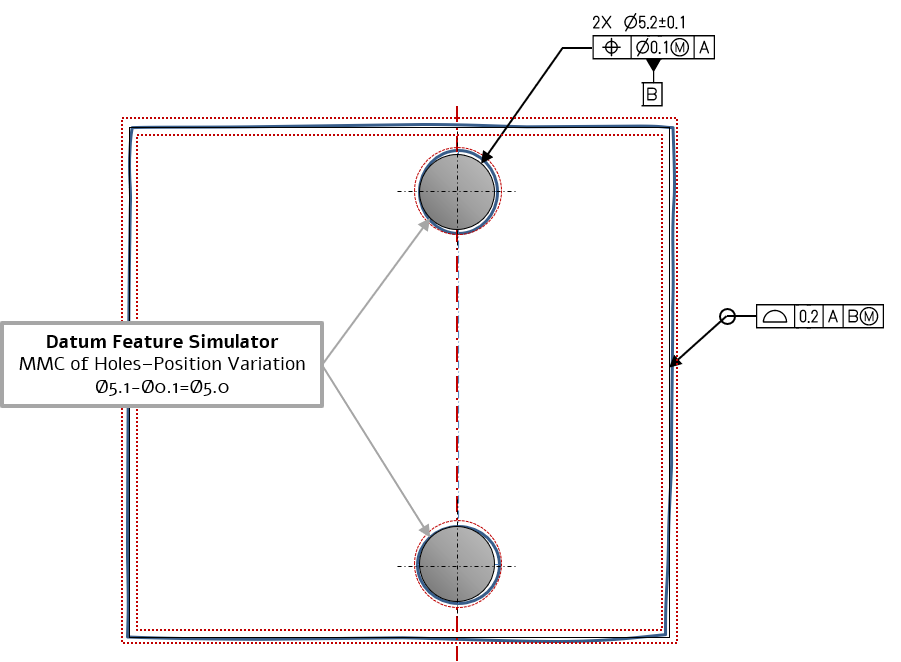
Figure 7
Datum B at MMB \ MMVC (ASME, MMB – Maximum Material Boundary; ISO, MMVC – Maximum Material Virtual Condition) may allow some Shift (displacement) between the holes and the datum Simulator.
Since, in this case the Shift allows the external boundary to meet profile specification, the part is good, and should not be scraped!!!
In this case the drawing specification is a realistic description of reality, in reality the part is located simultaneously by two pins.
The drawing does not forbid the initial procedure taken (locate to one hole and alighn by the other) parts that will pass inspection following this procedure are good!
But if a parts fails inspection,
then Datum Shift should be inspected to avoid scrapping a Good Functional part!!!
Bottom Line
Even if we did something “a thousand times” and “everyone” understands what it means,
it may be common and accepted,
But still nothing more them “Tribal Knowledge”
Geometric Tolerances are a tool to define Geometric Functional Requirements
State Standard & Revision to assure proper Decoding
Write to get it Right


