This tip complies with ISO GPS and ASME GD&T
The following Tip is based on a true case shared by Machinix Manufacturing. Machinix engineers took our GD&T\GPS training course and found that proper application of GD&T is a key to reduce quality and functionality risks.
This Tip shares a successful application of GD&T savvy 🙂
Machinix is a customer success oriented manufacturer, and while working on a quotation for a part, found that the customer drawing is ambiguous and parts produced to specification may not function properly. Original drawing is seen in figure 1
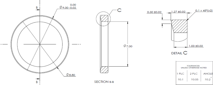
Since the drawing is a Plus\Minus drawing:
- It is impossible to tell the primary features of the part (what feature dictates the primary directions)
- The conic surface is indirectly toleranced, which may yield to a situation where parts that pass geometric verification may not be functional.
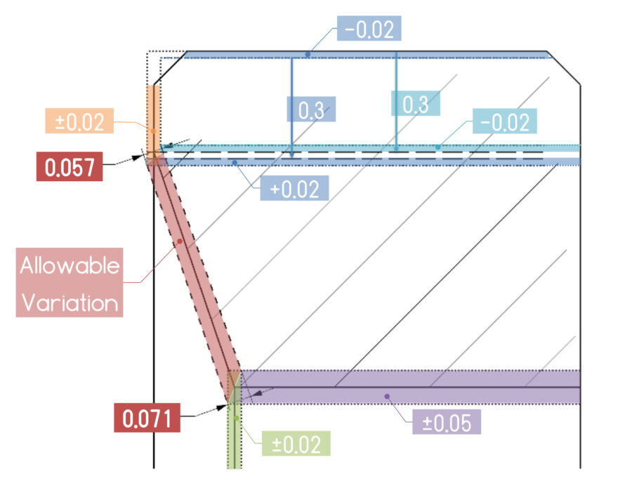
Figure 2 shows a possible interpretation of variation limits. A part that will be within these boundaries will pass geometric inspection, and be at functional risk. the conic taper appears to be a critical feature
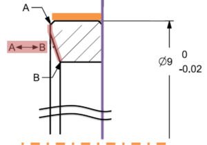
A request for clarification from the customer brought up the functional constraints documented in Figure 3:
- The part lies tangent to an opposite planar surface (marked in purple)
- The part is centered by the outer cylindrical diameter 9 (the axis line of the orange surface)
- Original drawing no direct specification to the conic surface (the area marked in red in Figure 3 between marker A and marker B), the conic and flat are critical features of the part
- The red area should not exceed a symmetrical offset of 0.015mm (In the original drawing, this area could reach the limits of 0.057 – 0.071).
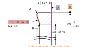
Considering this, Machinx’s recommendation (Figure 4) was to update the drawing,
- Specify purple and orange surfaces as datum features.
- Add direct specification to the critical surface (red) with a profile (instead of plus minus).
(Profile directly specifies a zone that limits size, position, position, and shape variation of the critical features (marked by the red zone in figure 4, and is simpler to control)
Machinix developed a digital platform (figure 5) that manages Quotation, Technical issues, and Approvals, to rapidly mitigate risks and resolve any technical issues ensuring all issues are resolved without ambiguity before production.
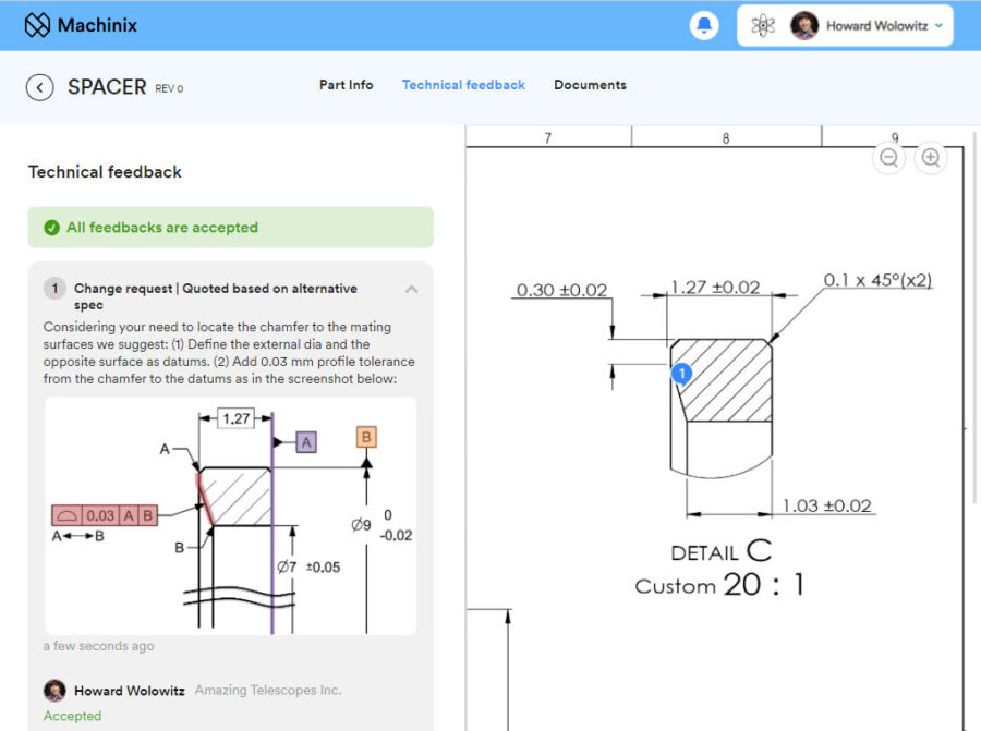
*Machinix is a digital platform for the procurement of precision machining parts, which at the quote stage gives technical feedback, including reference to the application of geometric tolerances, on the blueprints.
Bottom Line
Geometric specifications (ASME GD&T and ISO GPS) are the tools to prescribe geometric variation limits to assure functionality of a manufactured part.
Standard Geometric Specifications allow us to specify even complex requirements in clear unambiguous manner, no need to “reinvent the wheel”.
In cases of uncertainty, consult an expert (save the time and cost of “reinventing the wheel”, misinterpretation, rework…)
Geometric Tolerances are a tool to map Functional Requirements to Geometric Limits
State Standard & Revision to assure proper Decoding.
Write to get it Right.

