The Top Plate, in the caster wheel assembly (Figure 1) locates & Orients the two axle supports
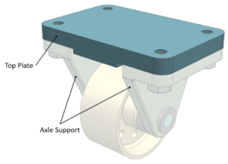
Figure 1
Partial Front View below (Figure 2), depicts intended Design constraints:
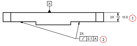
Figure 2
- Strength and Rigidity requirements lead to Nominal Pad thickness of 12 mm, and ±0.5 thickness variation is acceptable, since it will not impair Rigidity or weight constraints.
- The wheel needs to rotate Parallel to the floor inducing a Parallelism requirement on The two pads, Functional parallelism variation to the Top Surface (Datum Feature A) should be within 0.1 mm.
Measurements of a produced part are shown in Figure 3 (true surfaces in dark blue):
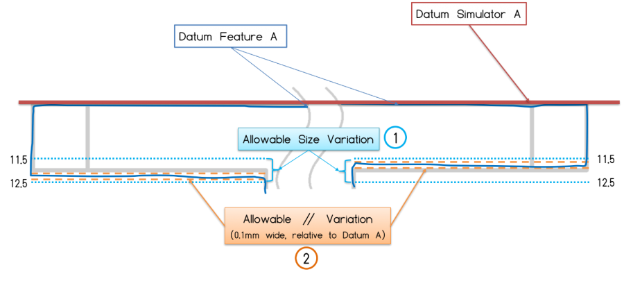
Figure 3
Both requirements are met, pad thickness is well within required thickness (11.5-12.5) and each pad is Parallel to Datum A within 0.1, but the part does not look right…
The problem is that the two Pads are not Coplanar, which may result in a height difference of up to 1 mm and misalignment of the axle supports.
As to the drawing there is no such requirement, since
Parallelism does not locate!!!
Each Pad Tolerance Zone is required to be independently oriented to Datum A.
To properly state that Coplanarity is also required Profile Control will be the appropriate specification. Note there are differences between the standards:

Figure 4
ASME:
- Profile control locates features to each other.
- Decimal delimiter – Period
- Number of Feature followed by – Capital X
ISO:
- Profile Specification requires CZ symbol to combine the tolerance zones and locate the features to each other.
- Decimal delimiter – Comma
- Number of Feature followed by – x
Proper specification in both standards yields the following requirements to be met:
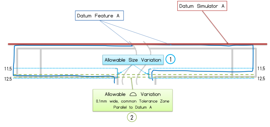
Figure 5
As to the revised drawing, the previous part fails inspection, since both Pads need to be within a Common Tolerance Zone compiled of two parallel planes 0.1 mm apart Parallel to Datum A, inducing Coplanarity between the two Pads and Parallelism of both pads to Datum A.
Bottom Line
Even if we did something “a thousand times” and “everyone” understands what it means,
it may be common and accepted,
But still nothing more them “Tribal Knowledge”
Geometric Tolerances are a tool to define Geometric Functional Requirements
State Standard & Revision to assure proper Decoding
Write to get it Right !
Questions? Ideas? Suggestions?
Write to us – info@TES-tec.net

