There is some ambiguity regarding meaning of the geometric control COAXIALITY. This tip is intended to resolve any disagreements on the subject, and I thank Aviram for raising this question.
The source of the different interpretations given to this symbol can be understood in light of the different meanings it has in ASME standard and in ISO standards; in addition, there is a mix-up with CONCENTRICITY, which we will discussed on a different occasion.
The simplest way to check the meaning of a geometric tolerance is to examine two things:
- Which element is controlled
- The shape, size, position and location of the tolerance zone
COAXIALITY according to ISO
According to the ISO standards,![]() indicates a specific function of
indicates a specific function of ![]() , and defines COAXIALITY as a situation in which the axis line (Median Line) of the controlled surface maintains a cylindrical tolerance zone; the axis of the tolerance zone is parallel to the datum, and at zero distance from it.
, and defines COAXIALITY as a situation in which the axis line (Median Line) of the controlled surface maintains a cylindrical tolerance zone; the axis of the tolerance zone is parallel to the datum, and at zero distance from it.
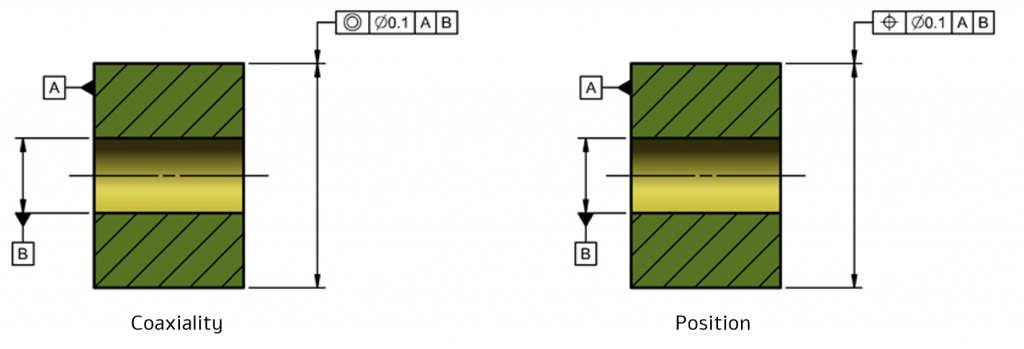
In both cases, the controlled element is the Median Line and the Tolerance Zone is a 0.1-diameter cylinder that is parallel to Datum B and is located at zero distance from it. Therefore, per ISO standards, there is no difference between the two figures in terms of the design requirement or the required control.
The following figure shows the meaning of the requirements according to ISO
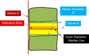
- Datum A – a plane with which the surface (Datum Feature A) comes into contact
- Datum B – the axis line of the block cylinder (Datum Simulator B) that is perpendicular to Datum A
- Tolerance Zone – a 0.1-diameter cylinder whose axis is common to Datum B
- Median Line – a non-straight line connecting the midpoints obtained from the outer surface by sections that are perpendicular to Datum B
COAXIALITY according to ASME
According to ASME, Coaxiality is a situation in which an axis line of a feature is common to the axis of a datum or of another feature.
According to the ASME standard, the symbol indicates CONCENTRICITY, and the element controlled is the Median Points; unlike which could control the center of a sphere, an axis, or a center plane.
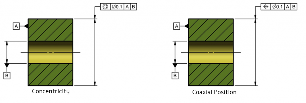
According to the ASME standard, only the figure on the right controls COAXIALITY (CONCENTRICITY will be discussed separately), the controlled element is the axis of the smallest block cylinder (AME – Actual Mating Envelope), as illustrated in the following figure:
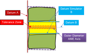
- Datum A – a plane with which the surface (Datum Feature A) comes into contact
- Datum B – the axis line of the block cylinder (Datum Simulator B) that is perpendicular to Datum A
- Tolerance Zone – a 0.1-diameter cylinder whose axis is common to Datum B
- Axis – the axis (a straight line) of the smallest block cylinder (AME – Actual Mating Envelope)
In summary:
COAXIALITY is a requirement for the location of a Median Line according to ISO, or of an Axis according to ASME.
Per ISO, the symbol ![]() indicates a specific function of
indicates a specific function of ![]() and the two symbols are interchangeable as a COAXIALITY requirement.
and the two symbols are interchangeable as a COAXIALITY requirement.
According to ASME, COAXIALITY is defined only by the symbol ![]() .
.
(Per the ASME standard, the symbol ![]() indicates CONCENTRICITY, and controls Median Points.)
indicates CONCENTRICITY, and controls Median Points.)
Bottom line is,
Even if we did something “a thousand times” and “everyone” understands what it means,
it may be common and accepted,
but it does not make it conform to a standard!

