Plane – Hole – Slot
References: ASME Y14.5-2009 \ 2018, ISO 5459:2011
Dowel pins are commonly used to locate and orient parts, in most cases corresponding hole and slot features are in the counterpart. Although ASME GD&T and ISO GPS standards are quite clear about the proper specification, there are some creative drawings going about.
The following tip started when I was called to resolve a dispute between Workshop and Engineering
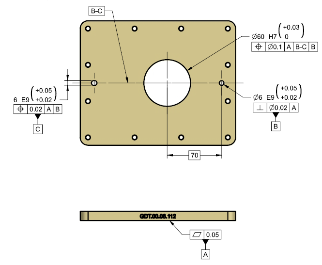
Dispute went over a similar drawing to Figure1 (simplified partial drawing).

Figure 1
What is the problem with the drawing?
Workshop returned the drawing to Engineering with the following clarification requests:
What is the meaning of |A|B-C|B|?
What does the Annotation B-C with the leader to the centerline stand for?
The Designer was sure the workshop is just stalling for time because he was sure the drawing is clear and unambiguous.
Workshop swore they are not trying to gain time, and truly the drawing is not up to any Tolerancing Standard, and it is not clear
The Resolution
Designer claimed the drawing is very clear!
The part is bolted to a counter part, with two dowel pins to locate it
- The part should be laid on the surface marked as Datum Feature A
- Centered to the common plane established by the hole and the slot (marked as B-C)
- The Origin is at the Hole marked as Datum Feature B
- The B-C annotation was added for clarity
Since location and alignment are achieved by two Dowel Pins.
Datum Feature B (the hole) has precedence over Datum Feature C (the slot’s two parallel planes), since the hole locates the part on the mounting surface & the Slot stop rotation.
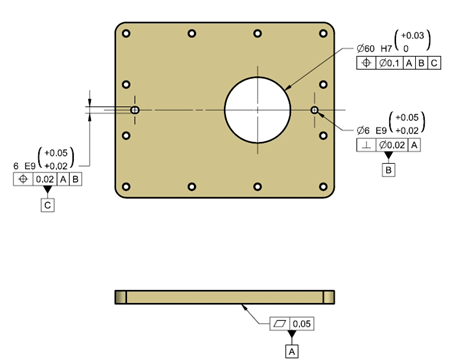
The standard correct way to specify the above intent is as to Figure 2.

Figure 2: Standard Specification
GD&T and GPS Standards, state a Datum Symbol should point to a physical surface. Datum features and their precedence order simulate functional specifications.
As to these ground rules:
- Datum A – arrests 3 Degrees of Freedom (2 Rotation, 1 Translation)
- Datum B – arrests two more Degrees of Freedom (2 Translation)
- Datum C – arrests the last Degree of Freedom (1 Rotation Tangent to A about B Axis)
So it appears Datum Features A and B are not Common So the correct Datum Reference Frame is |A|B|C|. and the B-C annotation is meaningless, adding only confusion.
Bottom Line
After clearing the matter and correcting the faulty drawing the Animal 1965 Hit “Don’t Let Me Be Misunderstood” came to my mind.
Even if we did something “a thousand times” and “everyone” understands what it means,
it may be common and accepted,
But still nothing more them “Tribal Knowledge”
Geometric Tolerances are a tool to define Geometric Functional Requirements
Write to get it right !
Questions? Ideas? Suggestions?
Write to us – info@TES-tec.net


