(ASME Y14.5-2009, ISO 1101:2012) Orientation deviation is controlled and measured against a Datum Reference Frame, or in short – DRF. The datums and the reading sequence define how the item should be positioned for inspection. Normally, the selection of datums and the reading sequence illustrate the part’s functional assembly constraints. Inspection is carried out against the DRF. Figures 1 and 2 present two alternatives for controlling the orientation of the part’s surface on the right:
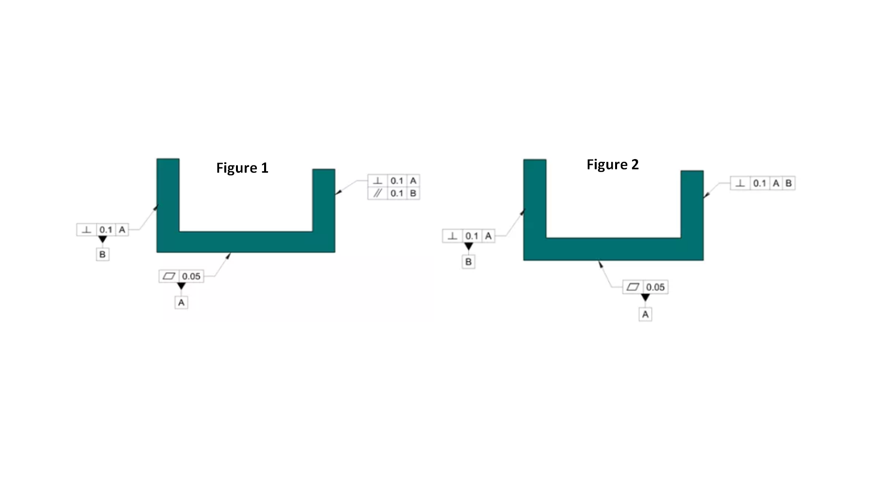
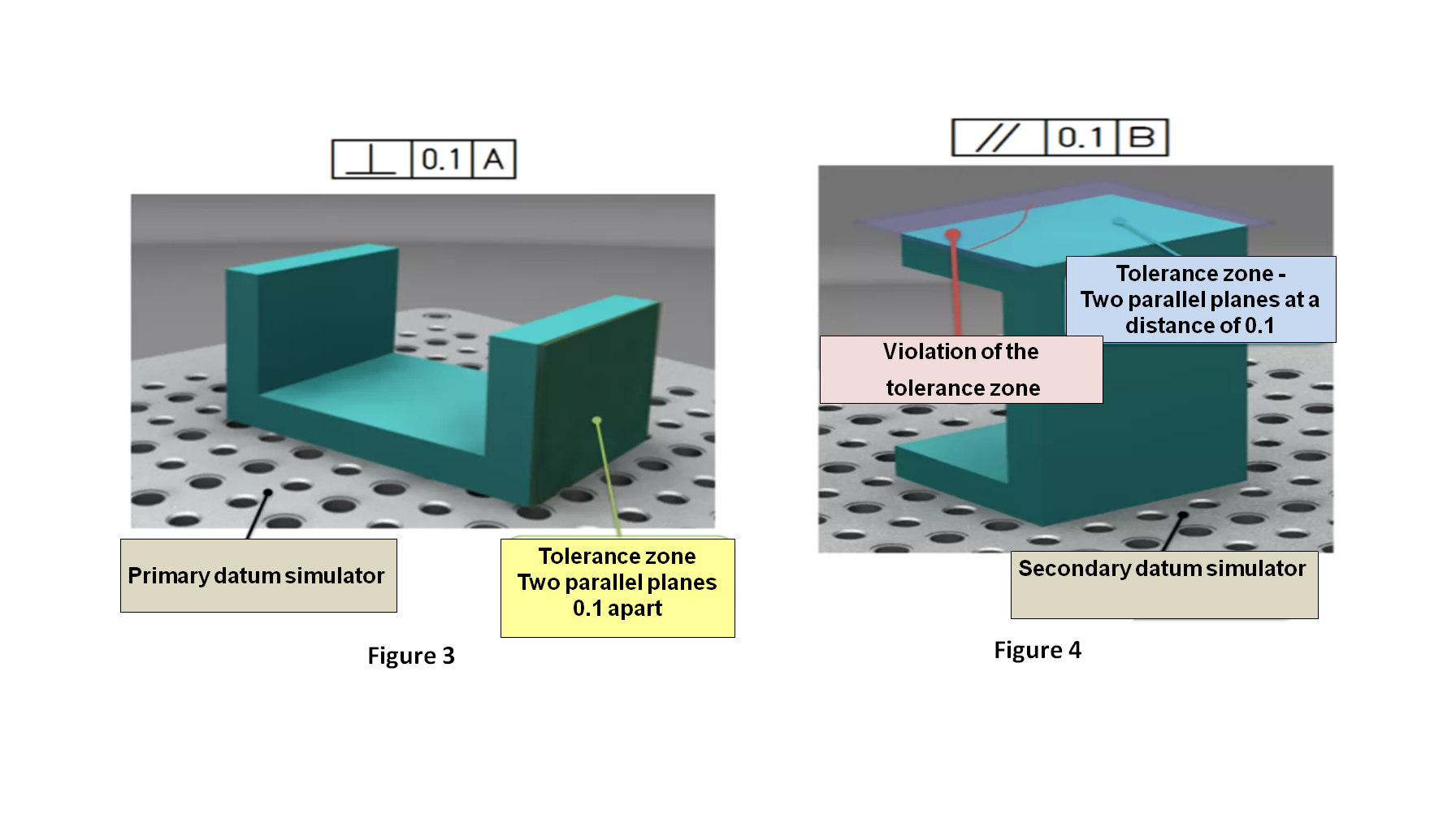
Each requirement (perpendicularity, parallelism) is inspected separately and the positioning is done independently; both requirements need to be met. In the example above, the item inspected meets the perpendicularity requirement (Figure 3), but does not meet the parallelism requirement (Figure 4).
In Figure 2, there is one requirement: The part needs to be positioned for inspection in the sequence specified, only then checked for compliance of the tolerance zone: First, the surface marked as Datum A feature needs to be placed on a plane, and only then the surface marked as Datum B feature should be attached to the plane, perpendicular to A.
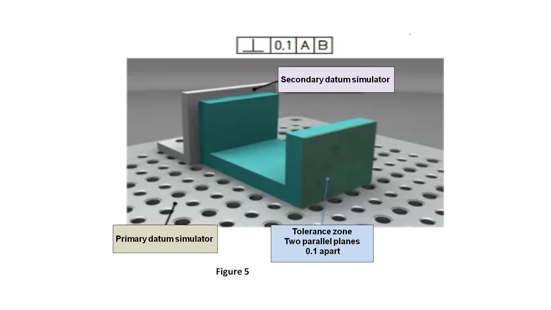
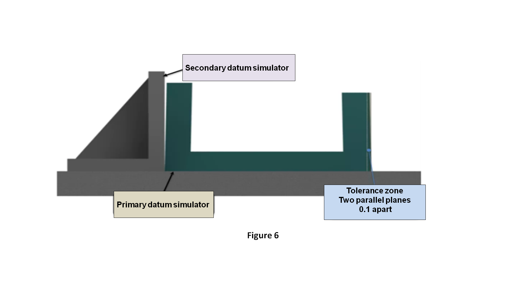
In this example, the same item that failed to meet the independent parallelism requirement (Figure 4), does meet the positioning orientation requirement |A|B| (Figure 5). The mystery is cleared when we view it from the side (Figure 6), in the item controlled, there is a perpendicularity deviation on the left surface (Datum feature B) relative to the base plane (Datum feature A). This deviation does not affect the measurement of perpendicularity / parallelism of the right surface because the measurement is against the DRF (rather than the physical surface) and the angle that simulates Datum B is perpendicular (per the measurement accuracy level) to plane A.
In summary: There is a difference in functional requirement between the two drawings Figure 1 illustrates a situation in which a part has two functional interfaces that are independent of one another; Figure 2 illustrates a situation in which the part has a single interface through which Datum feature A enforces the part’s assembly orientation.
Write to get it right !
Questions? Ideas? Suggestions?
Write to us – info@TES-tec.net

