What is the difference in meaning, if any, between the different forms of notation?
(This tip complies with ASME Y14.5-2009 and ISO 5459:2011)
Datums Reading Order
Datums reading order can be considered in a manner similar to assembly constraints in a CAD program (e.g. Mates). The difference is, that in a CAD program, the constraint works on a pair of perfect elements (one plane in relation to another…) and a datum reference system links a physical, imperfect element (surface, for example) to a high precision simulator (granite plate…) of a perfect theoretical element (plane).
Since there are no deviations in a CAD system (such as size, location, shape, or position), the order of application of the constraints would not change the result in the assembly. On the other hand, in a physical (real) part we are guaranteed a deviation in all four geometric characteristics (size, location, position and shape). The reading order will change the result obtained.
In the figure below the two cylinders are marked as datum features; the meaning at this stage is that this surface will serve as the basis for the construction of a datum (a datum by definition is an exact theoretical element).
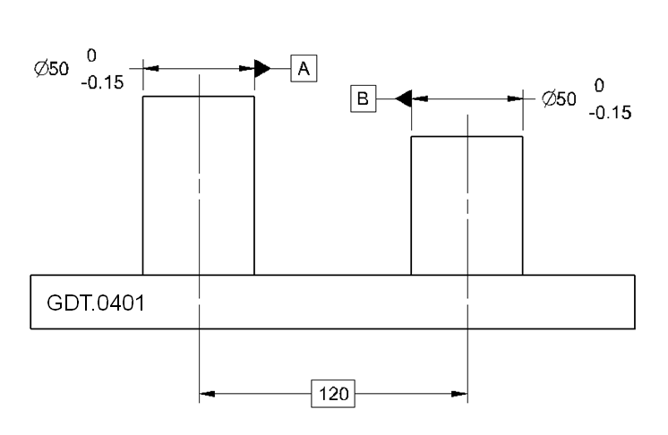
In the figures below, the part is shown with position and location deviations, and three alternatives are presented for using the A and B datums. In each of the alternatives the result is significantly different!
Alternative One (first A, then B)
- The first datum constraints four degrees of freedom (two for movement and two for rotation) and determines the position of the part.
- The second datum, although an axis as well, constraints only one more degree of freedom (rotation around the first axis).
- Five degrees of freedom in total.
Although the two datum features (A and B) are identical in the drawing (a cylinder sized 49.85-50.00), it is expected that the diameter of the cylinder blocking datum feature B (orange) will be larger than the diameter of the cylinder blocking datum feature A (red), since the location and position of the cylinder axis blocking datum feature B will be determined according to the cylinder axis blocking datum feature A, and any deviation in location or position of datum feature B, would be compensated for by enlarging the diameter of the blocking cylinder.
Note: The dimension controls the size of the physical surface; it does not control the diameter of the datum simulator!!!
Alternative Two (first B, then A)
- The first datum constraints four degrees of freedom (two for movement and two for rotation) and determines the position of the part.
- The second datum, although an axis as well, constraints only one more degree of freedom (rotation around the first axis B).
- Five degrees of freedom in total.
You can easily see that in the real world (which is not perfect) the position of the part is different than the position illustrated in the first alternative. And in this case, there is a higher probability that the blocking cylinder of datum feature A will be larger.
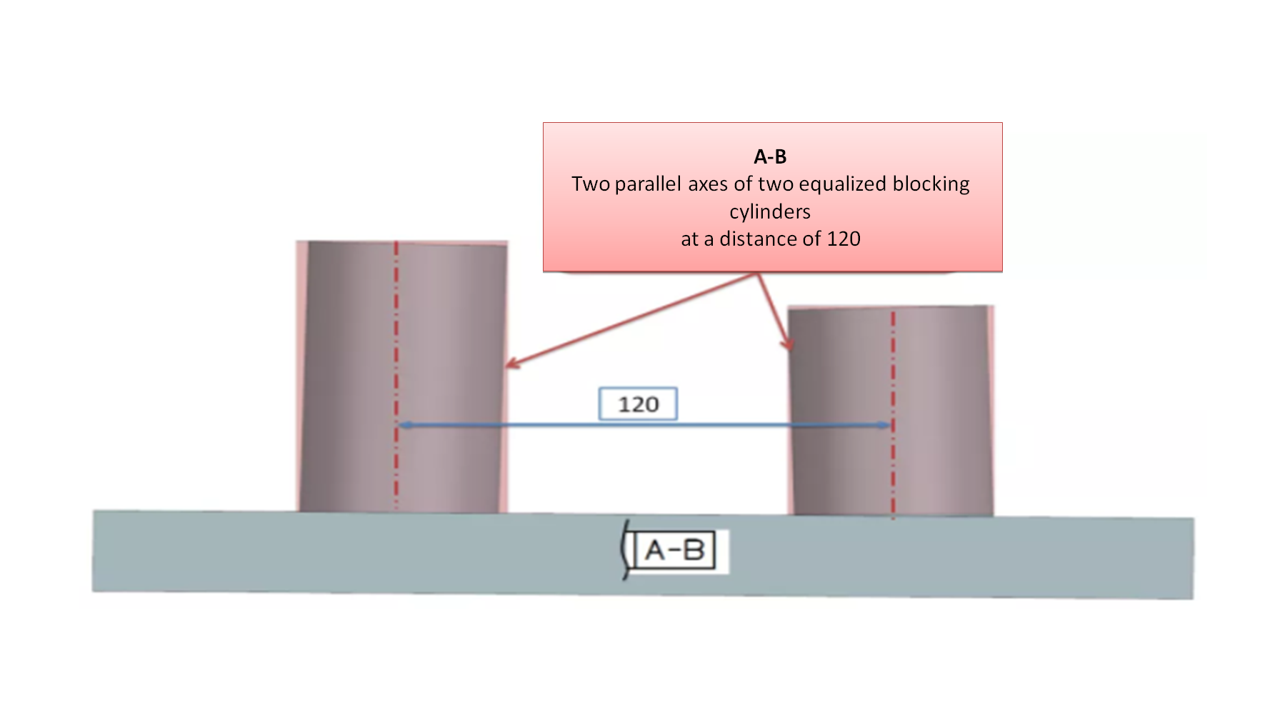
Alternative Three A-B
Unlike the two previous alternatives in which the first datum has precedence over the next, the notation ‘A-B’ indicates that the two datums are equal in value and importance, and that both must be found simultaneously (not one after the other).
- The two axes together constraint five degrees of freedom.
This alternative may be more challenging to implement than the previous two because the two datums A and B are equivalent and must be found simultaneously, while maintaining the balance of deviations between the two physical surfaces and the diameter of the datum simulator.
At the design level, the differences between the standards are not significant, but for inspection purposes, especially with CMM software, you should make sure that the software interprets the reading according to the required standard.
(ASME, ISO – Similarities and Differences – not in this post…)
What is the Correct Reading?
Datums and reference systems are designed to simulate functional constraints to the location and position of an item. The correct reading is the one which reflects the intent of the design as closely as possible, and identifies the features and their order of importance.
Questions? Ideas? Suggestions?
Write to us –info@TES-tec.net

