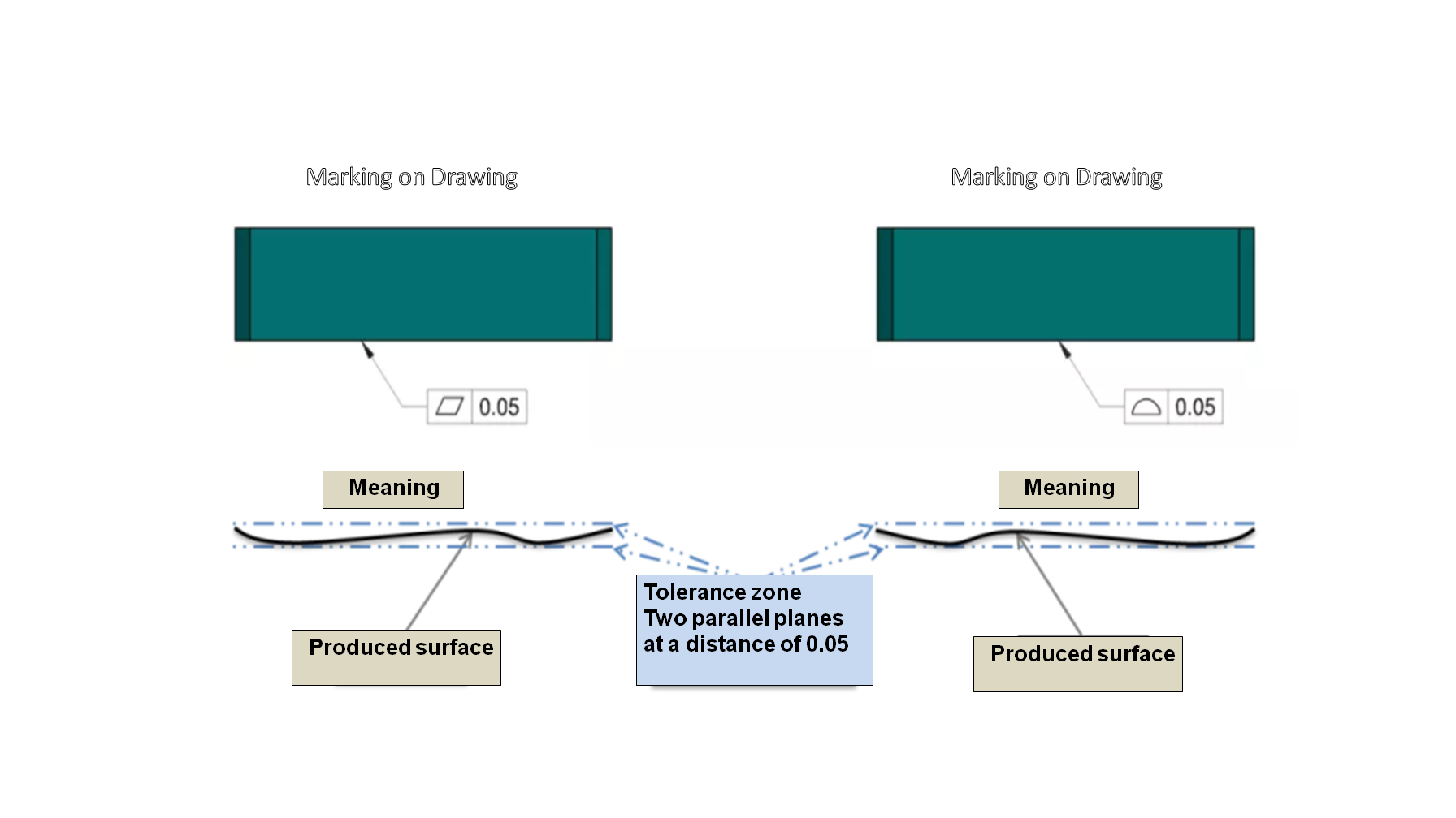
(ASME Y14.5-2009) Among the GD&T symbols there are overlapping areas, in some cases there is no difference in functionality when applying one control method or another. The figures below present two alternatives for an adapter plate. The design intent is that the bottom side is the main interfacing surface of the part and it has to maintain a flatness of 0.05. In Figure 1, the controlled element is a single surface, in both cases the tolerance zone is: two parallel planes with a distance between them of up to 0.05.
Figure – 1
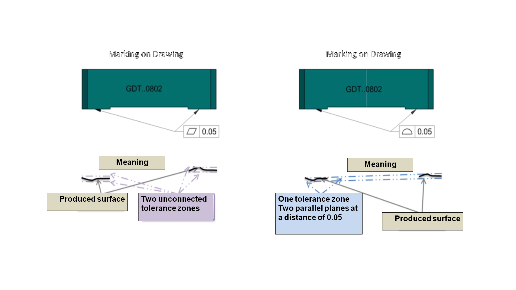
To improve the accuracy of the part’s assembly, a release was made between the desired contact surfaces in the assembly, and material was removed from the surface, leaving two contact surfaces that need to maintain a single plane in an accuracy level of 0.05, as presented in Figure 2.
The Profile symbol refers to the two surfaces as a pattern – therefore, since the two surfaces in the drawing have a common plane, the tolerance zone is also common to both surfaces, and the design intent is maintained.
Flatness is a tolerance used for form alone, and is not able to control position and orientation of surfaces (not even within a group). In such a case, each surface has an independent tolerance zone; Flatness controls the form of each surface separately, and does not control the position or the relative orientation between the two surfaces.

Geometric tolerances have been created to enable the specification of functional and unambiguous geometric requirements of an item; in order to convey the design intent, and to prevent the manufacturing of parts that pass inspection but are not functional, the change of design shown in Figure 2 requires the use of Profile to ensure that the two contact surfaces maintain a common plane at the level of accuracy required for the functionality of the item.
Questions? Ideas? Suggestions?
Write to us –info@TES-tec.net


