Angularity does not Locate
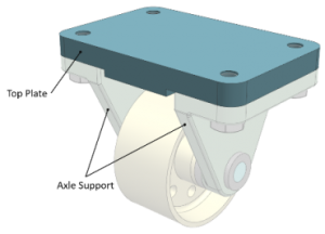
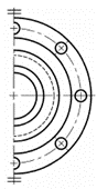
The Top Plate, in the caster wheel assembly (Figure 1) locates & Orients the two axle supports Figure 1 Partial Front View below (Figure 2),
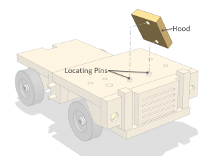
Hole Pattern as a Datum Feature
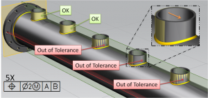
This tip complies with ASME Y14.5-2009, ISO 2692-2006 In many cases parts in an assembly are designed to mate simultaneously with more then one counterpart

Straightness per unit length
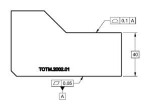
Straightness and flatness per unit length are required when it is necessary to avoid sharp changes over a feature’s length or surface unit. Figure 1
Symmetry & Center Lines are not the same
There is some confusion in the industry regarding Symmetry and Center Lines. I this Tip we will attempt to set things straight, as to ASME
Welded Assembly part 2
Reading a drawing – what are the permitted deviation limits? (ASME Y14.5-2009, ISO 1101:2012) This post is the second in a series dealing with a
Who’s afraid of Profile?
Tip in agreement with ASME Y14.5-2009 & ISO Standards At a recent visit in a machine workshop, one of the metrologists announced that “Engineering truly