As to ISO & ASME
Real world is not perfect, which is the reason geometric limits need to be specified to assure real part functionality.
This tip was triggered by a question raised by Rani in our GD&T whatsapp group: how to specify geometric variation of a slot, used to bend a semi flexible wire?
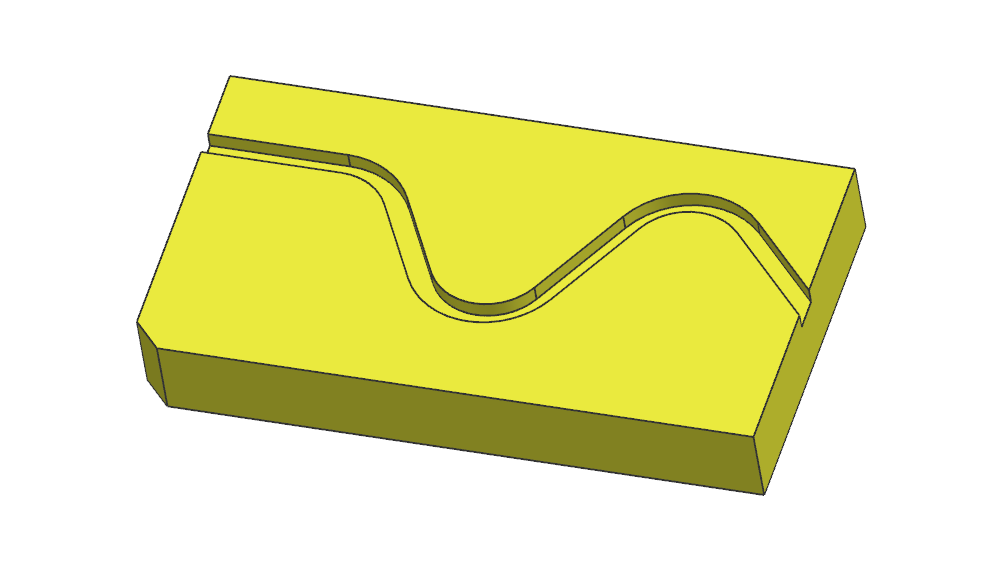
Figure1 shows a CAD model of the ideal Part

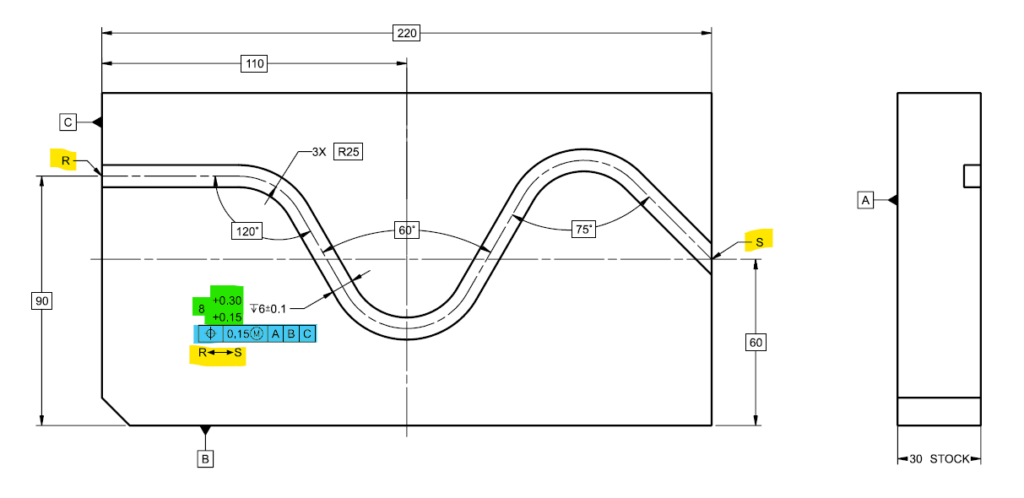
Functional need is to shape an 8 mm wire to the prescribed shape. Figure 2 illustrates the chosen solution:

The “between symbol” R↔S (marked yellow) indicates that the size (marked green) & position (marked blue) specifications apply across all the features between the designated extremities as a pattern.
The Basic (ASME) \ TED (ISO GPS) dimensions define the ideal slot spine (similar to CAD or CNC command).
Since the MMC boundary of the slot is of interest, position @ MMC (ASME) \ MMR (ISO GPS) is specified allowing bonus tolerance for manufacturing and optional GO gage for inspection.
Bottom Line
Geometric specifications (ASME GD&T and ISO GPS) are the tools to prescribe geometric variation limits to assure functionality of a manufactured part.
Standard Geometric Specifications allow us to specify even complex requirements in clear unambiguous manner, no need to “reinvent the wheel”.
In cases of uncertainty, consult an expert (save the time and cost of “reinventing the wheel”, misinterpretation, rework…)
Geometric Tolerances are a tool to map Functional Requirements to Geometric Limits
State Standard & Revision to assure proper Decoding
Write to get it Right


