(ASME Y14.5-2009, ISO 1101:2012)
Our monthly tip, following Idan’s question on how to indicate symmetry.
In Figure 1, the two threads on the front are illustrated as symmetrical to the symmetry line. Despite the dimensions noted in the drawing, the tolerance zone for the position of the holes is open to interpretation…
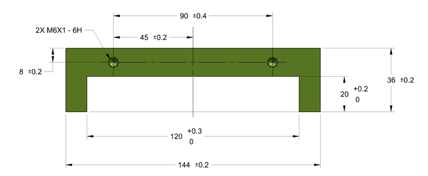
The symmetry plane is not completely unambiguous. In reality there will always be deviations in the exterior facets of the part (flatness, parallelism, distance). Which one defines the symmetry plane of the part?
* The center plane of the two outer surfaces (144)?
* The center plane of the slot (120)?
Figure 2 shows the deviation of position allowed according to the drawing in Figure 1.
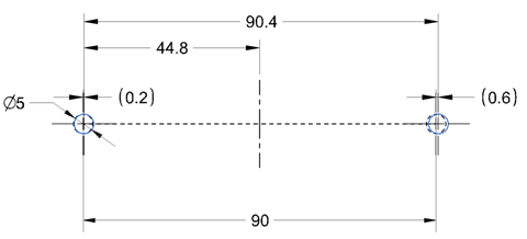
The maximum position deviation for the left thread position is 0.2 to the right or left, affecting the allowed deviation for the right thread from the theoretical position. The ‘half’ dimension does not improve the situation, but rather increases the deviation permitted.
If the functionality required is:
* the two threads should be at a nominal distance of 90 units;
* the horizontal position deviation between them should be 0.8 (±0.4);
* horizontal deviation from symmetry for the center plane between the two external facets (144) – 0.4 (± 0.2);
then a position tolerance of 0.4 according to Figure 3 accomplishes the three requirements in full:
* the theoretical position between the threads is 90 – a BASIC dimension (an exact theoretical size);
* the real axis of each of the holes must be within the diameter of a 0.4 cylinder, and the permitted tolerance for the distance between the holes is 89.6-90.4;
* the position of each individual hole is symmetrical to the center plane between the outer facets (144) in a tolerance zone of ± 0.2.
Figure 3In addition, the position tolerance addresses both the vertical dimension and the orientation deviation of the threads simultaneously.
Food for thought:
According to Figure 1, the permitted position deviation is ± 0.2 both horizontally and vertically;
it therefore follows that the radial deviation is the square root of the sum of squares in the horizontal direction and in the vertical direction
SQRT(0.42+0.42)=0.56
Is the original tolerance for the position too large and allows a deviation that leads to non-functionality?
Or can the position tolerance be increased to 0.56?
Questions? Ideas? Suggestions?
Write to us –info@TES-tec.net

