There is some confusion in the industry regarding Symmetry and Center Lines. I this Tip we will attempt to set things straight, as to ASME & ISO drafting standards.
Symmetry Line
- ASME Y14.2-2014 para. 4.8
- ISO 128-30:2001 6.2
To save time and space, symmetrical objects maybe drawn as a fraction of the whole. Symmetry Lines identifies the parts symmetry planes. An example is shown in Figure 1:

Figure 1
This practice has become very rare in industry since in CAD systems creating a partial view of a symmetric part may be more time consuming to produce.
Center Lines
- ASME Y14.3-2014 para. 4.7
- ISO 129-1:2018 3.1.1
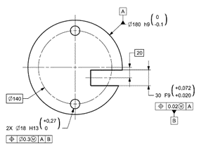
Center Lines when used, represent axes, center points or center planes of symmetrical parts and features and also bolt circles. See examples of center lines in figure 2.

Figure 2
Bottom Line
Symmetry Lines are part related and an archaic relic of manual drafting.
Center Lines are feature related, each feature of size may have a center line representing its derived feature
Even if we did something “a thousand times”
and “everyone” understands what it means,
it may be common and accepted,
But still nothing more them “Tribal Knowledge”
Geometric Tolerances are a tool to define Geometric Functional Requirements
State Standard & Revision to assure proper Decoding
Write to get it Right


