Locate Surfaces to be Tangent or “lower”
As to ASME and ISO GPS
Tip based on consultation request by an automotive R&D engineer:
How to specify the following requirements as to geometric tolerancing standards (note, images are partial, for demonstration purpose only).
Problem description
The Engineer described the following scenario:
Two parts: base & cover intended to be joined by Ultrasonic Welding on the perimeter lip (“Weld Pad Surface”}.
Joint should withstand pressure so two bosses were added in the center. “Weld Boss Surfaces” shall also be joined by Ultrasonic Welding

Figure 1
Weld Boss Surfaces MAY be tangent to Weld Pad Surface Plane but SHALL NOT be higher then Weld Pad Surface Plane.
We explained the requirement to the supplier using presentation slides and a verbal explanation, but we wish to document the geometric specification in the drawing using standard GD&T and ISO GPS.
Solution:
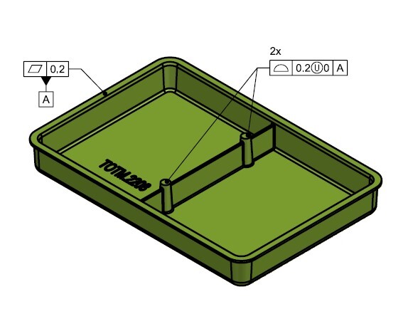
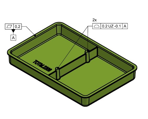
Functional requirement is that relative to a Plane “Weld Pad Surface” is tangent to, the two internal “Weld Boss Surfaces” SHALL be within that Plane and second parallel plane 0.2 mm offset “down”.
As to ASME (see Figure 2), Profile is to only tool to locate integral surfaces, and in this case the profile is Unilateral (only down).
The nonnumeric value following the U modifier specifies how much of the profile tolerance zone is “out” of the nominal model material, in this case Zero.

As to ISO GPS (see Figure 3) Profile may be used to locate planar surfaces, and to specify a Unilateral tolerance zone modifier UZ is used.
The nonnumeric value following the UZ modifier specifies the offset of the tolerance zone center relative to nominal model, the minus sign states the tolerance zone center offset is “In” the nominal model.

Figure 3
Bottom Line
Geometric specifications (ASME GD&T and ISO GPS) are the tools to prescribe geometric variation limits to assure functionality of a manufactured part.
Standard Geometric Specifications allow us to specify even complex requirements in clear unambiguous manner, no need to “reinvent the wheel”.
In cases of uncertainty, consult an expert (save the time and cost of “reinventing the wheel”, misinterpretation, rework…)
Geometric Tolerances are a tool to map Functional Requirements to Geometric Limits
State Standard & Revision to assure proper Decoding
Write to get it Right


