Are geometric tolerances only applicable for machining?
(ASME Y14.5-2009, ISO 1101:2012)
This tip’s frame story is a fable, but the lessons learned are real.
The divider’s body (feeder) is based on a standard pipe (NPS 10 SHD 100), a flange, an end cap (standard catalog components), and outlets.
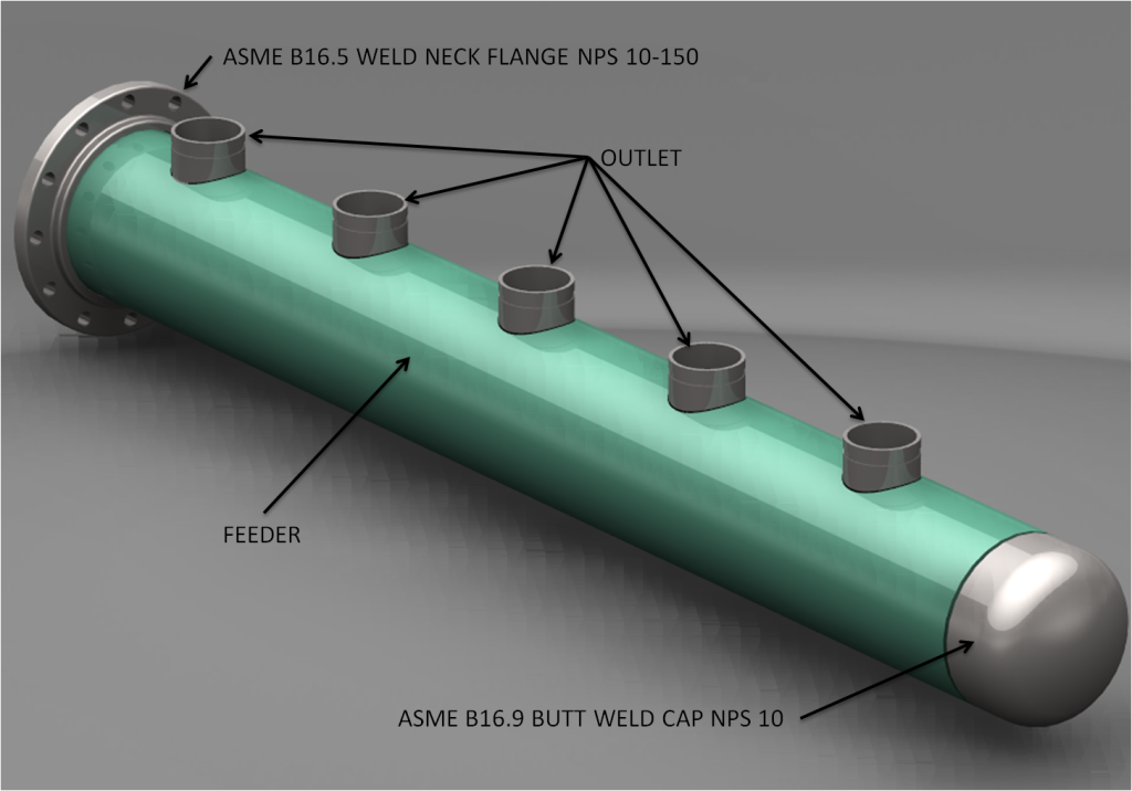
The feeder part was produced in the past according to the following drawing:

ב
Following the replacement of a subcontractor, it was claimed that the required accuracy greatly increases the cost of the part. A check of similar flow dividers produced in the past showed that:
– documentation of dimensions measurement was not required (as it increases costs).
– the actual dimensions of the parts have significant deviations in respect of the drawing requirements.
– The assembly time required for the flow divider on the ground is longer than expected.
– The assembly teams on the ground hate these flow dividers and each team developed its own assembly methods.
– No one has said anything, because “it’s always been like that…”
The main causes for the difficulties in assembly are deviations in the position of the holes in the direction perpendicular to the axis of the body (up / down in Figure 2), the deviations in parallelism between the outlets, and also in the perpendicularity of the outlets in relation to the axis of the body (the feeder).
(By the way, even if there had been a requirement for measuring dimensions, the deviations in the position perpendicular to the axis and in the angle of the outlets in relation to each other would not have been reported. There is no definition of the deviation permitted!!!)
Following the check conducted, the functional geometric requirements were clarified:
– The basic functional installation elements are: The axis of the body and the surface of the flange;
– A deviation of a radius of 1 from the precise theoretical position of the holes is within the limits of the deviation allowed for the assembly.
– It is important to maintain only the internal limit, a diameter of 114.5 in a precise theoretical position (an NPS-4 pipe according to the catalog – 114.3±0.5%, the upper limit is 114.8715, but experience has shown that the probability of a diameter higher than 114.5 is very low).
Figure 3 shows the updated specification. Unlike Figure 2, in which the permitted position deviation of the holes was defined by a tolerance dimension (±1) relative to the left surface only, the current position tolerance allows a deviation in a diameter of 2 (radius: 1) in all directions.
The position control also delimits the angular deviation permitted (diameter: 2).
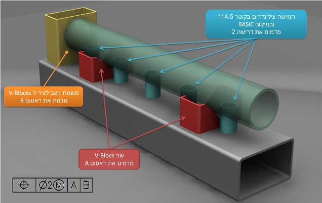
The (M) modifier permits an increase in deviation of position, the more the size of the hole increases from its MMC mode (extreme state for assembly – the smallest hole). A set of five cylinders with a diameter of 114.5 (the MMC mode of the hole 116.5 – position deviation in MMC diameter 2 = Virtual Condition 114.5).
Another significant difference between Figure 2 and Figure 3 is that the datum reference frame (datum A followed by datum B) clearly describes the functional constraint and unambiguously defines the positioning for inspection.
Figure 3 – Flow Divider Body
There was concern about the supplier’s reaction, but after the meaning of requirement 2 (MMC makes it easier, not stricter) was explained, the supplier was satisfied. Especially after it was found that the inspection gage shown in Figure 4, is suitable for inspecting the fulfillment of requirement 2 as to the position of the holes.
It is important to remember that geometric tolerancing (GD&T) is a tool for translating functional requirements into geometric requirement specification for the part.
(Providing tolerances according to a specific technology rather than according to the need, may lead to requirements that are expensive and without functional meaning.)
Also, geometric tolerances define what is needed!
Not how to produce or how to check it.
Qestions? Suggestions?Ideas?
Write to us – info@TES-tec.net

