Reading a drawing – what are the permitted deviation limits?
(ASME Y14.5-2009, ISO 1101:2012)
This post is the second in a series dealing with a welded assembly of a flow divider. (This tip’s frame story is a fable, but the lessons learned are real.) This post deals with reading the requirements in the assembly drawing and translating those requirements into permitted deviation limits.
First, it is important to bear in mind that the requirements specification (drawing) defines what would be the theoretical measure of deviation that would not affect the functionality of the item (under the responsibility of the designer).
Secondly, just as a geometric requirement does not necessarily require (unless explicitly specified) a specific technology (milling, engraving, casting, injection, three-dimensional printing…) or process (e.g. in machining: tool, spindle speed, feed rate, coolant…),
also the method of inspection (tools, positioning, number of measurements, etc.) should be professionally considered and determined by the tester.
Or, in other words, a drawing illustrates the functionality required of the finished item, what is needed! Not how (to produce or check it).
This post is about ‘what’ (what the meaning of the requirement is).
The question of ‘how’ (to carry out inspection) will be discussed in another post…
(although, in this case, there is no difference in the definition of the datum reference frame and the geometric requirements between ASME Y14.5-2009 and ISO 1101:2012 standard, there are differences in the physical inspection definitions!)
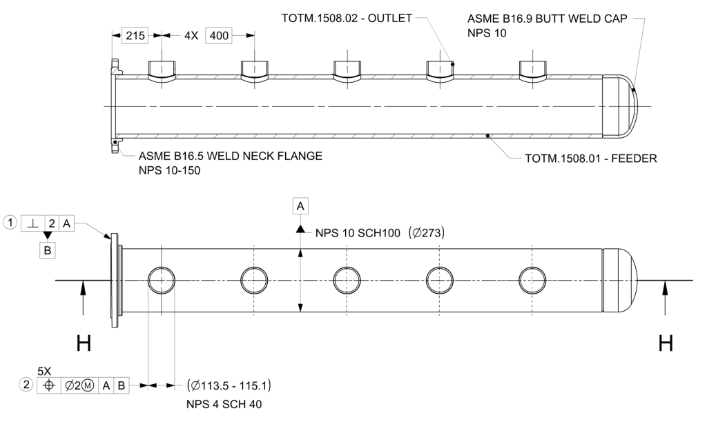
Assembly Drawing – Geometric Requirements Specification.
The drawing is partial, and for highlighting purposes, only two views are presented, showing only the geometric requirements relevant to the location and position (orientation) of the flange and the outlets.
All dimensions are in millimeters.
What are the requirements at the theoretical level?
The following figures present a part (with deviations) against the deviation limits permitted according to the drawing (Figure 1). In the first stage, the part should be fixed in space according to the datum reference frame definition.
- Datum Reference Frame
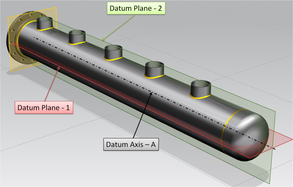
The datum reference frame consists of three perpendicular planes. The datum reference frame defines the zero point for the control as well as the measurement directions.
The relation between the datum reference frame and the part is defined in the drawing:
1.1 Datum A
- Datum A is the common theoretical line when cutting two theoretical planes (the red and the green).
- In the part produced – the axis of the outer shell is located on datum A.
- Datum A – constraints 4 degrees of freedom (2 movement, 2 rotational).
1.2 Datum B
- Datum B is the third plane (yellow) in the datum reference frame which is perpendicular to the two datum planes (red and green).
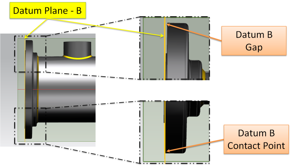
- In the part produced – between the datum-B plane and the outer surface of the flange there is one point of contact.
- Datum B – constraints one more degree of freedom (movement along axis A).
-
Figure 3 – Interface between Datum-B Plane and the Surface of the Flange
It is important to keep in mind:
- The datum reference frame is theoretical and precise (without deviations or uncertainty).
- Geometric tolerances are measured from the planes of the datum reference frame.
- The resulting space between datum B plane and the surface, does not affect the results of measurements that relate to the datum reference frame!
2. דרישות גיאומטריות
2.1 דרישה מספר 1 – ניצבות משטח הפלאנז’
באיור 4 מוצג אזור החריגה המותר למשטח. משטח הפלאנז’ חייב להמצא בין שני מישורים מקבילים, שמרחק בינהם הוא שתי יחידות והם ניצבים לציר דאטום A.
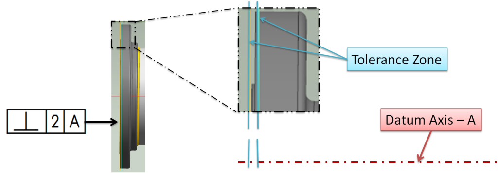
- The first point of contact with the tolerance zone plane in this case is shown in Figure 3;
- In Figure 4 we see that the entire surface is contained within the tolerance zone, i.e. meets the requirement.
2.2 Requirement Number 2 – Position
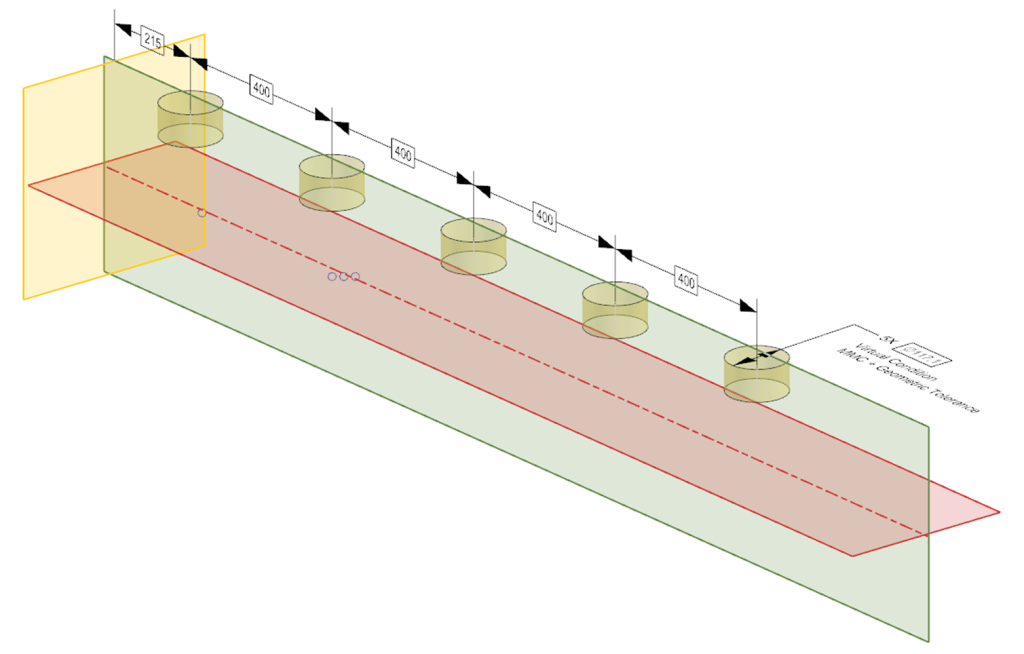
- Requirement number 2 controls the five outlet pipes simultaneously. The position control relates to the datum reference frame defined according to A and B.
-
Figure 5 – Position Tolerance Zone - The M Modifier changes the position requirement to one-sided; the outlet should not deviate from the perimeter of the extreme state diameter (the Virtual Condition).
- Extreme state = diameter ∅ 115.1 in Maximum Material Condition (MMC maximum diameter according to NPS standard) + maximum position deviation permitted in Maximum Material Condition, a Ø2 diameter cylinder.
- The result is five cylindrical envelopes with a diameter of 117.1, in a precise, theoretical location and position in relation to each other and to the datum reference frame defined (A|B), which all five outlet pipes must maintain simultaneously.
-
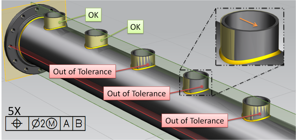
For inspection, the item is placed against the datum reference frame and checked to see whether the requirement is fulfilled. Figure 6 shows the positioning of a part produced for inspection of the location of the outlet pipes.
-
In the part shown in Figure 6, three of the outlet pipes are in deviation. In the part shown in Figure 6, three of the outlet pipes are in deviation.
This part is rejected! An examination revealed that the deviation is mainly in location along the axis (in the direction of the orange arrow). If the item is usable (even with this deviation) then the drawing must be updated, in order to avoid rejecting usable parts again in the future!!!
In summary
- Geometric tolerances define the requirements from the finished part!!!
- Geometric tolerances define perfect theoretical elements.
This post dealt with the translation of requirements into theoretical limits, leaving at this stage the options for physical inspection implementation open.
In principle, physical inspection of geometric requirements can be said to have three main alternatives:- Set-up (blocks, prisms, dial indicators…);
- XYZ measuring machine (CMM);
- Fixtures (Go-NoGo).
Food for thought:
- Can the location of the outlets be controlled by using a Go-NoGo gage?
- If so, what would the gage look like?
-
Questions? Ideas? Suggestions?
Write to us –info@TES-RnD.com

