This tip complies with ASME Y14.41-2003, ASME Y14.41-2012, ISO 16792:2006
Since the mid-1990s, software tools for design, production, and inspection are based mainly on three-dimensional digital models. As a result, sharing of a three-dimensional digital model is increasingly in addition to or in place of a two-dimensional drawing.
Sharing digital models saves time (rebuilding a three-dimensional model from a two-dimensional drawing) and significantly reduces the risk of errors (reading a drawing is becoming an extinct art).
The model is theoretical and precise, but reality is not perfect, and it is necessary to define deviation boundaries that will not impair the functionality of the finished part.
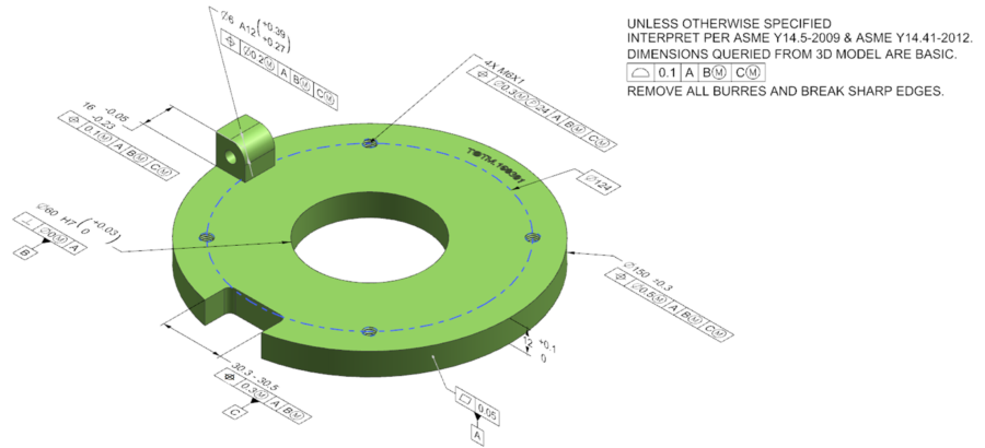
Figure 1 presents a three-dimensional model that also includes geometrical dimensions and tolerances
Figure 1
Although the technology already exists for sharing three-dimensional models that include all requirements for execution (3D PMI – Product Manufacturing Information), the common solution is still a combination of a model and an accompanying drawing. The model is used to describe the ideal geometry and the drawing defines deviation limits (tolerances for sizes and geometric tolerances) that would not impair the functionality of the item.
Since the model and its deviation limits (in a 2D or a 3D drawing) describe the same item, there must be no mismatch between the model and the drawing.
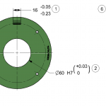
Figure 2 shows only the drawing dimensions and the dimensions’ deviation limits in two views:
Figure 2
Every feature has to be defined with deviation limits. If so, what should the size in the model be?
For this question and others, ASME Y14.41 was written, adopted with slight modifications also by the ISO standards, and published as ISO 16792.
The standards specify two modes, depending on the way the dimension tolerance is written:
• a dimension written as a nominal value and limits ± (bilateral, unilateral) such as dimension #1, the dimension in the model must be equal to the nominal value;
• a dimension written as limits, such as dimension #4, the dimension in the model can be any size within the range.
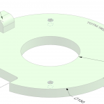
Figure 3 shows the values that should be in the model according to the standard:
Figure 3
In this example, since all dimensions except the width of the notch are written in the nominal form, the size in the model must be in the nominal value.
For the LIMIT dimension, the size of the model is in the range between the minimum and the maximum 30.3-30.5.
The logic of the standards for dimensions in Solid is along the same lines as the wave / hole tables; Balloon 6 points to a nominal hole diameter of 6 millimeters and a tolerance which is plus, plus.
Of course, BASIC dimensions, which are precise theoretical dimensions, such as the diameter of the threads’ division circle, the position of the 6mm-diameter hole in relation to the reference system… must be represented in the model at their exact theoretical value.
And what about threads? Which dimensions, if any, must be specified? Should you round off dimensions that are downloaded from the model?…
All this and more in the standard, and in our advanced course: Setting Dimensions and Tolerances in 3D / Reduced Dimensions Drawings.
Questions? Ideas? Suggestions?
Write to us –info@TES-RnD.com

