Requirements To Geometric Specification method, developed by Gili Omri, is a straightforward, practical workflow. Aligning product level functional requirements to clear unambiguous geometric specifications, utilizing either ISO-GPS or ASME GD&T Geometric Dimensioning and Tolerancing Standards.
How to Document and Interpret geometric product specification
Mechanical design solution geometry (CAD Model) and overall Variation Limits (Tolerance Budget) are derived from Top Level Product Requirements. To assure functionality of a mechanical system each part should meet the Designated Geometric Specifications.
TES Method cuts the path from Product Requirements to Part Geometric Specification, by a three step processes:
Datum System: Establishes the functional reference frame of the part, simulating physical assembly constraints, that the part features are located and oriented to and relate datum features as to datum precedence order.
Key Features: Located to Datum System and set geometric variation limits to all features that significantly affect product function, assembly, safety or part manufacturing processes.
Non-Key Features: located to reference frame and set default geometric variation limits to all other features (may be driven by manufacturing process).
Let’s see how it works:
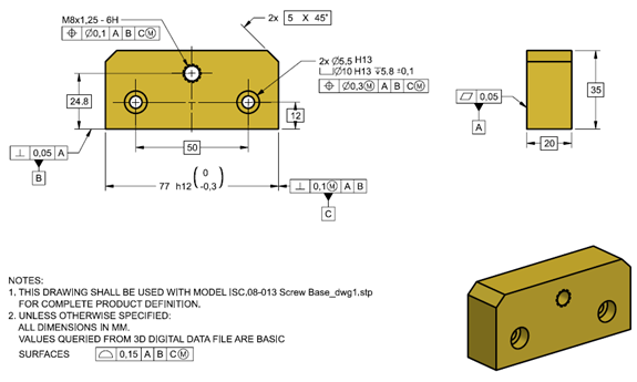
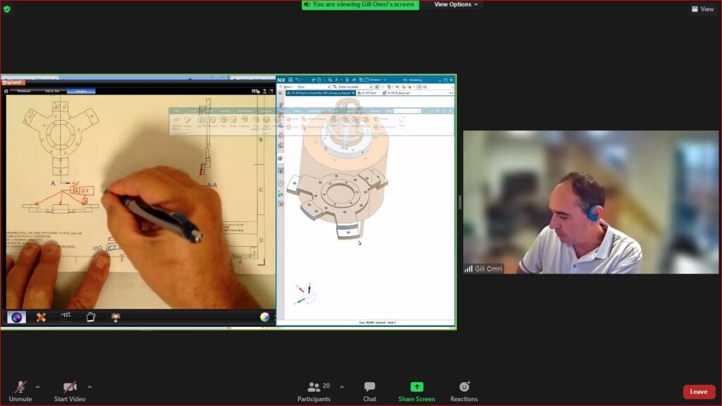
TES-Method Example The Screw Base Part (yellow part in Figure 1)
Figure 1 Part thread advances the clamp drive screw
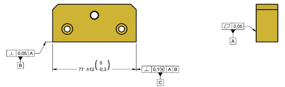
Primary Datum System
Datum system depicts functional constraints, arresting rotation & translation degrees of freedom as in real world assembly.
Datum features are controlled relative to each other as to the functional precedence order!
Figure 2
Primary Datum Feature A: mount face, has only Form variation controlled by flatness.
Secondary Datum Feature B: should be flush to table, orientation to A & form controlled by perpendicularity
Tertiary Datum Feature C: part symmetry plane, perpendicular to A & B
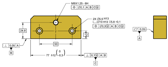
Key Features
Key Features are critical features to the parts function. In this case the M8 driving thread and the two socket head counter bore holes.
Driving Threads location variation is controlled by position relative to relevant datum system. The Socket Head Holes are controlled in the same manner.
Non-Key Features
All features that are needed (otherwise not modelled or fabricated), have a secondary effect on part function. Non-Key features are most likely to be controlled by a general profile tolerance related to the main datum system.
Figure 4
לפרטים על ההשתלמויות בטולרנסים גיאומטריים מלא את הטופס מטה או צור קשר info@tes-tec.net 074-704-7060